

PID方法如何保护压缩机从飙升and choke?
应用范围:先进控制避免危险苏尔ges to centrifugal and axial compressors. Processes described make it easier to find optimal PID settings using standard tuning routines that can be the basis for autotuning and makes it easier to implement adaptive control. See diagrams, equations.
Learning Objectives
- Learn how to optimize proportional-integral-derivative (PID) settings using standard tuning routines that can be the basis for autotuning, to make it easier to use adaptive control.
- Safety requires a compressor surge margin — the space between operation and surge — without choking the compressor.
- A PID application has drawback, but it can be optimized by using angles instead of projections.
PID application tuning insights
- Find out how to optimize proportional-integral-derivative (PID) settings using standard tuning routines that can be the basis for autotuning, which makes it easier to implement adaptive control.
- The role PID plays in compressors, aviation and aerospace engine design might not be widely known, but it is crucial for efficiency, precision and safety.
The rapid development of aviation, which began in the last century, required even more powerful and economical engines, in which compressors play an important role. Since compressor surge has potentially catastrophic consequences, great attention always has been paid to the prevention of this phenomenon. Proportional-integral-derivative (PID) feedback controllers can help.
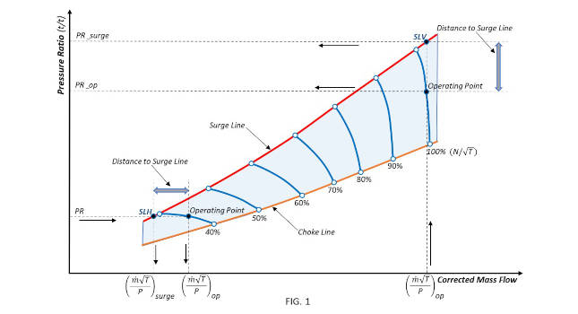
NASA research on jet engine compressors included extensive field and wind tunnels testing followed by data analysis in coordinates typical of aerodynamic experiments, presenting compressor maps of total pressures ratio versus corrected mass flow, as shown in Figure 1.
The total pressure is the sum of the static and dynamic pressures. Figure 1 shows a hypothetical compressor map that includes constant speed performance curves that can vary greatly in shape and slope; surge and choke limit lines. The ratio of total pressures on the vertical scale and the corrected mass flow on the horizontal scale form a reference rectangular coordinate system for comparing compressor prototypes.

Figure 1: NASA research on jet engine compressors included extensive field and wind tunnels testing followed by data analysis in coordinates typical of aerodynamic experiments, presenting compressor maps of total pressures ratio versus corrected mass flow. Courtesy: Roman Bershader
Maintain a compressor surge margin, the space between operation and surge
To assess the risk of operation of compressors behind the surge line, a parameter called surge margin was introduced, which is a quantitative characteristic of the space between the operating point and the surge point located on the same performance curve. Given that jet engine compressors run on air, hence a constant molecular weight substance, the corrected mass flow rate is proportional to the input Mach number, which is a dimensionless quantity defined as the local velocity divided by the speed of sound in that medium. This parameter, which is one of the similar criteria used in gas mechanics, turned out to be critical for studying how stall flow patterns behave in the same way under the influence of the compression ratio at certain Mach numbers, regardless of other variables.
Compressors in jet engines, industrial compressors
For compressors operating at sea level, such as industrial compressors, the static pressure can exceed the dynamic pressure by two orders of magnitude. For such compressors, the ratio of static pressures (Rc)is more suitable as a vertical scale. Industrial compressors also often use differential pressure sensors to measure flow.
Dimensionless non-measurable (but calculated) value(∆P/P), which is defined as the pressure drop ∆P across a given type of flowmeter divided by the static pressure at the location of the flowmeter, which is proportional to the square of the Mach number. The dimensionless value (∆P/P) can be used as a horizontal scale for compressor maps. Then, in the coordinate system of the ratio of static pressures and the dimensionless calculated value (∆P/P) and the boundary of the unstable gas flow, the surge line turns out to be independent of the molecular weight of the substance. This operates under the assumption the specific heats ratio does not change much.
PID feedback controllers adjust an anti-surge valve, discharge throttle valve
The rectangular coordinate system, by definition, positions the operating point relative to the surge and choke lines using projections onto the axis. This can be used to convert the two-dimensional representation of compressor operation into a one-dimensional process variable PV that can be used for control. PID feedback controllers are the most practical and are commonly used to protect compressors by adjusting the anti-surge valve to prevent surge line crossing or by adjusting the discharge throttle valve to prevent choke line crossing.
The surge protection and choke protection PID controllers continuously calculate the error value (ER)as the difference between the desired setpoint (SP%)and the input process variable (PV%)to update the controller output. For this reason, the surge and choke lines must be stored in the compressor control system as table functions. The operating point (OP) position must then be calculated from the input signals from the flow and pressure sensors, after which thePVcan be determined.
For nearly vertical performance curves, as shown in Figure 1, the concept of “surge margin” in a rectangular coordinate system is defined as the distance between the projections of two points on the vertical axis: the surge point (SLV)(the point of intersection of the vertical line drawn from the operating point to the surge line) and theOP.
For flatter performance curves, as shown in Figure 1, which is the most common characteristic of industrial compressors, the concept of “surge margin” is defined as the distance between the projections of two points on the horizontal axis: One is theOPand the second is the surge point (SLH)(the intersection point of the horizontal 1 line drawn from the operating point to the surge line). The rectangular coordinate system sets limits for determining the actual distance between an operating point and a surge point located on the same performance curve.
Safety threshold corresponds to the safety margin
As shown in Figure 2, the actual surge margin cannot be equal to the distance to the surge line. However, the compressors are protected by calculating the PVs, according to formula (1) or similar:

Formula (1) calculates a process variable comparable to the safety threshold that must be set for rectangular coordinates when the actual distance, surge margin, is measured along the performance curve. Therefore, to achieve maximum efficiency, the safety threshold must be chosen in such a way so it corresponds to the actual safety margin. Thus, the rectangular coordinate method does not provide an explicit setpoint selection, and the selected fixed setpoint may not be suitable for different performance curves.
最推荐industri安全阈值al compressors is about 10%, measured from the surge line to the operating point at a given pressure ratio. As can be seen from Figure 2, the desired safety threshold,SP,应该是set above 10% to correspond to a safety level of 10% of the actual surge margin. How much higher than 10% depends largely on the shape and slope of the performance curves and the slope of the surge line.

Figure 2: The actual surge margin cannot be equal to the distance to the surge line. Courtesy: Roman Bershader
PID drawbacks in formula 1
Despite the success of protecting compressors with the methods described by formula (1) or similar ones, they have some drawbacks:
The first of these is the distance between the operating point and the surge line stored in the compressor control system cannot be equal to the actual distance between the operating point and the surge point on the performance curve to which both points refer.
Since the projection of flatter performance curves onto the vertical axis, or the projection of nearly vertical performance curves onto the horizontal axis (as shown in Figure 1) can have a very narrow range of change, where a small change in the vertical coordinate causes a large change in the horizontal coordinate and vice versa.
Sensitivity to the slightest changes can lead to instability in the control system. Stabilizing the system in such a case can only be achieved by slowing down the PID controller, which leads to an expansion of the safety threshold, followed by unwanted recirculation or blow-off.
Another disadvantage is if an increase in flow is required to protect the compressor from a surge, then the increase in the flow parameter in equation (1) is squared (in other similar algorithms, for example, in the Compressor Controls Co. algorithm – formula (2), the parameter related to increase in flow is squared and put in the denominator).
This creates a non-linear relationship between thePVand the flow rate, making it difficult to tune a PID controller that should, under all circumstances, prevent surge line crossing and be less dependent on additional open-loop response.

Plant automation personnel often set assignedSPsfor PID controllers that receive input, calculate PVs, and send output to drives according to plant operation. Visualization of the position of the operating point on the compressor map, as shown in Figure 1, does not quantify compressor performance, which is limited by proximity to surge and throttle choke. This makes it difficult for operators to assess the risk of manual intervention if necessary.
Use angles instead of projections for PID
These shortcomings can be significantly corrected in a different coordinate system by using angles are used instead of projections when the rectangular coordinate system is replaced by a polar coordinate system. In a two-dimensional polar coordinate system, each point on the plane is defined by a distance from the origin and an angle from a reference direction. To obtain a reference point – the origin of coordinates, it is necessary in Figure 2 change the vertical coordinate fromRcto (Rc-1) and change the horizontal coordinate from∆P/Pto the square root of∆P/P, which is proportional to the similarity criterion in gas mechanics, the Mach numberMa.
The new polar coordinate algorithms described in U.S. Patent No. 11,434,917 offer more effective surge and choke protection than any other known method.
第一种方法使用极坐标是reminiscent of the assumption in equation (2) where the surge line has a constant value of one, but in polar coordinates the surge line is assumed to have a constant angle. To do this, the vertical coordinate (Rc-1) should be replaced by a function of (Rc-1), as shown in Figure 3. ThePVcan then be calculated as a percentage:

A commonality of formulas (1), (2) and (3) is that the process variable is calculated and then the selected setpoint is measured against the surge line by the “minimum flow” rule regardless of the compressor operating range. The available compressor capacity is determined by a set of constant-speed performance curves with minimum flow points on the left (surge points) and maximum flow points (ideally choke points) on the right.
Optimizing the performance curve, safety margins
Operation of the compressor can then be described by moving the operating point in the direction of minimum or maximum flow along the performance curve, or by moving from one curve to another along a variable radius measured from some imaginary origin, as shown in Figure 4.

Figures 3 and 4: At left, the first approach to using polar coordinates is reminiscent of the assumption in equation (2) where the surge line has a constant value of one, but in polar coordinates the surge line is assumed to have a constant angle. To do this, the vertical coordinate (Rc-1) should be replaced by a function of (Rc-1). Then, in Figure 4, compressor operation can be described by moving the operating point in the direction of minimum or maximum flow along the performance curve, or by moving from one curve to another along a variable radius measured from some imaginary origin. Courtesy: Roman Bershader
The method shown in Figure 4 was obtained by converting rectangular coordinates (Rc-1) versus Mach number to polar coordinates, provided the radii from the center point to the minimum flow point and to the maximum flow point of each performance curve are equal. Thus, thePVcan be calculated for each radius in the range of movement of the operating point from minimum to maximum flow:

The process variable PV obtained from formula (4) converts the compressor map into a one-dimensional operating point offset scale from 0 to 100% shown in Figure 5, where the movement of the mark simultaneously determines the position of the operating point relative to surge and choke. Only this method of protecting the compressor allows scaling the entire range of compressor operation and can select the exact margins of safety in accordance with compressor capabilities.
Visualization and simultaneous quantification of operating point movement toward surge limit or choke limit based on full operating range scale enhances situational awareness, makes it easier for operators to understand potential risks, and increases productivity and efficiency.
The “high efficiency zone,” depicted in the diagram of the movement of the operating point, is the compressor’s maximum efficiency zone, the position of which is important when optimizing the performance of an individual compressor. The proximity to the “high efficiency zone” can be used as a universal process variable for serial and parallel compressors to share the load between them, optimizing the efficiency of a group of compressors.

Figure 5: The process variable PV from formula (4) converts the compressor map into a one-dimensional operating point offset scale from 0 to 100%, where the movement of the mark simultaneously determines the position of the operating point relative to surge and choke. Protecting the compressor in this way allows scaling over the range of compressor operation with ability to select the exact margins of compressor safety. Courtesy: Roman Bershader
High accuracy, autotuning, adaptive control
The methods presented in polar coordinates have the highest accuracy in determining the margin of safety compared to all known methods, since the margin does not depend on the slope of the compressor performance curves and is the same over the entire range of process conditions.
Polar coordinate methods provide faster PID control, allowing the compressor to be used over a wider range, which increases efficiency by minimizing recirculation or blow-off.
The process variable in these methods is nearly linear, making it easier to find the optimal surge and choke PID settings using standard tuning routines that can be the basis for autotuning, which makes it easier to implement adaptive control.
Polar coordinate methods aim to implement a new modern control strategy by updating the software and graphical user interface while maintaining the integrity of the input/output (I/O) signals and without the need for hardware and communication upgrades.
Roman Bershaderis a retired engineer, now consultant, with a bachelor’s and master’s degree in aerodynamics and a Ph.D. in experimental fluid dynamics who worked for Compressor Controls Corp. for more than 30 years. Edited by Mark T. Hoske, content manager,Control Engineering,CFE Media and Technology,mhoske@cfemedia.com.
关键词:PID、APC、压缩机的安全
CONSIDER THIS
How does this PIDapplication’s operating margin help your advanced process control applications?
Do you have experience and expertise with the topics mentioned in this content? You should consider contributing to our CFE Media editorial team and getting the recognition you and your company deserve. Clickhereto start this process.
